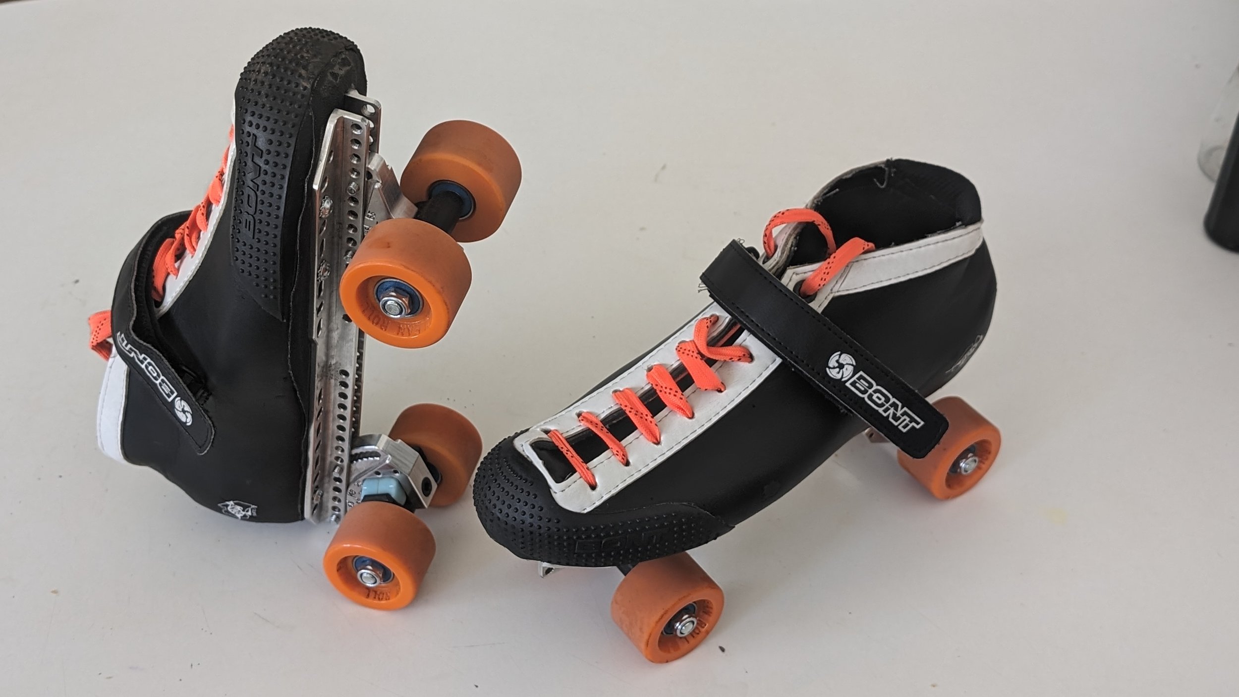
In a nutshell, this is the Version 2 of a project to create an adjustable wheelbase, adjustable steering angle roller skate plate.
The first “super adjustable skate plate” was frankly a little more successful that i was expecting. I was expecting a 6/10 or 7/10 result, but for my usage, was a 9/10!
That said, it did have some areas for improvement. Many of those are listed on that page.
I wanted to improve the design a little, and chose a few things to focus on.
Major Features Retained From Original
Adjustable steering angle, independent of wheel position
Adjustable wheel position, independent of steering angle
Easy adjustment (screws are on inside of each foot, so ergonomics are good to make adjustment with skates still on feet.)
Wide Adjustment range.
Goals
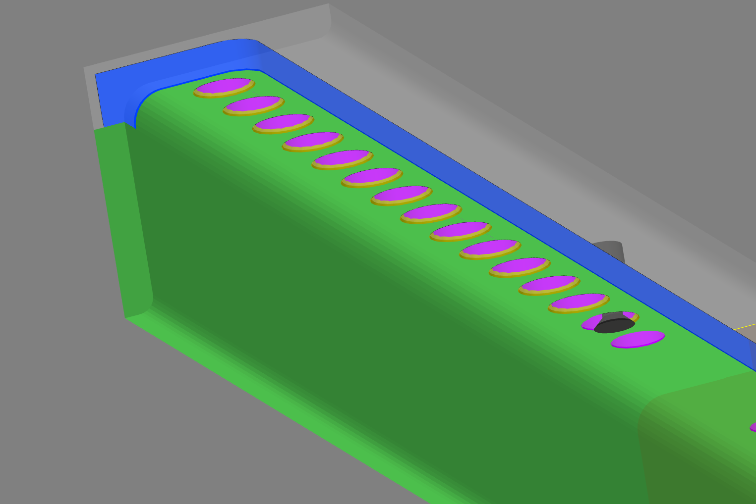
Lower deck height. The prior version was limited by a confluence of design decisions
The desire for 5* steering angle adjustment increments
The desire for complete holes (this leads to some increased safety. If the attachments bolts are loose, we don’t want the steering angle to move unpredictably.)
The resulting stacked arcs of holes at 5* increments.
This meant the total deck height was about 51mm, not terrible, but the lowest “normal” plates on the market are around 45mm.
Adjustment angles both above and below 45*
The V1 only had angles from 45 degrees down to 10 degrees. Smaller angles give more steering angle at lower lean angles.
Wheel-bite elimination
While i didn’t get wheel-bite on my first plates, with the lower deck height goal and increased steering angle, this was going to start being an issue.
Prettier
Prior version had some awkward looking ends to the arcs on the pivoting truck hanger, and had an overall square look.
All metric
The V1 plate uses Arius trucks, which use an m7 thread on the pivot axle, which has a 5mm internal hex head. It also uses 10-32 threads for the rail clamping bolts. Since i can’t control the OTS part, i wanted to switch to M5 threads on the rail clamping bolts.
Less rail stick-out
The existing plates can contact the ground on deep toe-toe manuals, which is something i really enjoy doing. At 45* steering angle on the only plates, this happens at something line 50-60 degrees tilted up from horizontal. Pretty good, but something that might be nice to improve on.
Results
lower!
But honestly the difference is only really about 5mm (which is ~0.2”). The Deck Height is now a touch under 46mm. That’s an improvement, but does come at a cost.
It’s required to use T-nuts inside the shoe, and to have button head screws attaching the plate to the shoe. This is because of clearance between the rail clamping screws and the shoe attachment screws is a limiting factor.
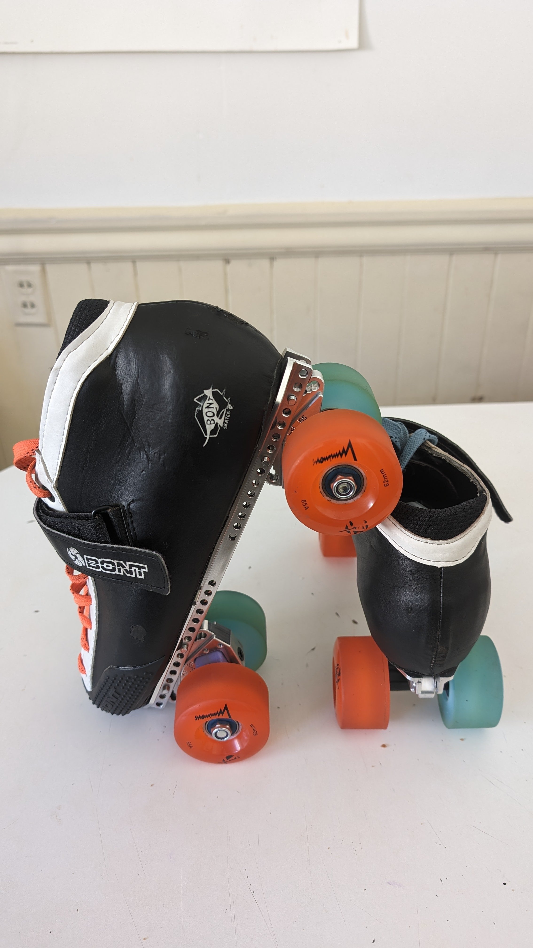
Below we see both the plate with traditional nuts, and then with buttonheads. The buttonheads just clear.

Lighter!
The v1 plate was 512g (with no axle nuts). The new one is 428g!
Compared to a 6.75in (~=165mm wheelbase) Pilot Falcon Plus plate, it’s a little heavier, but close. Amazingly, a stock Arius is around 360g in the same length!
If we compare my plate to the max wheelbase it can do, it’s almost identical to the Falcon Plus weight.


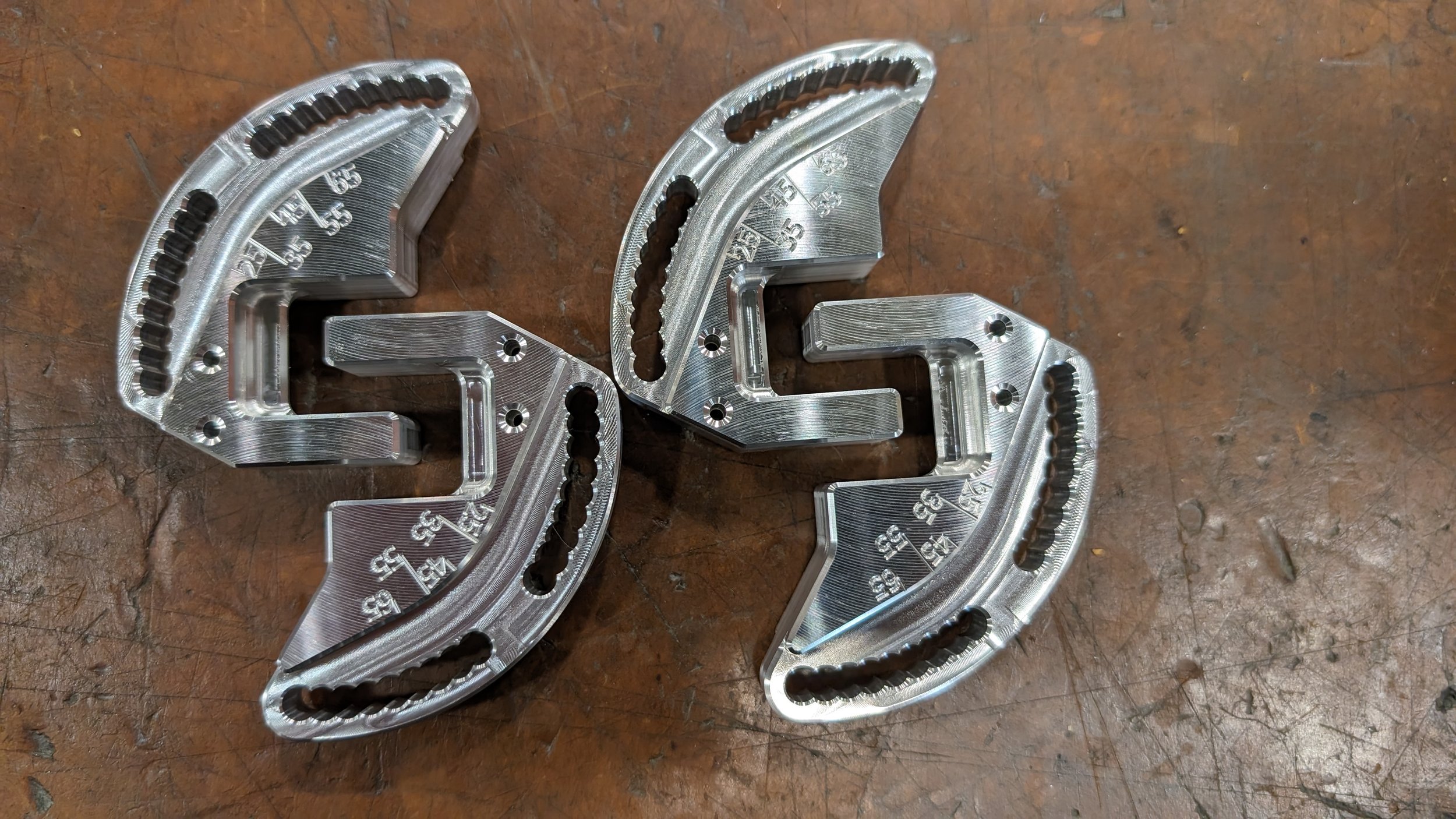
Prettier!
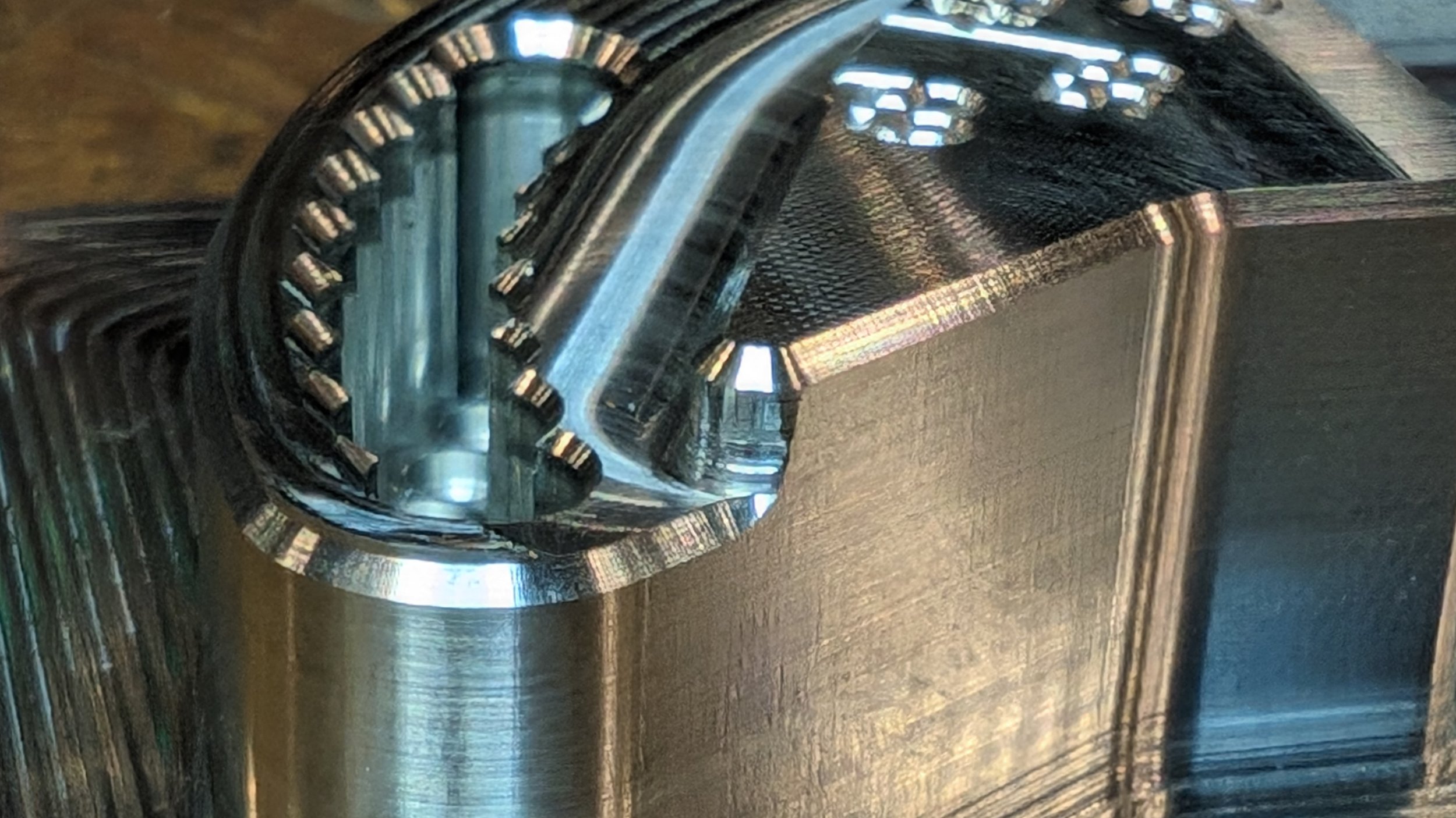
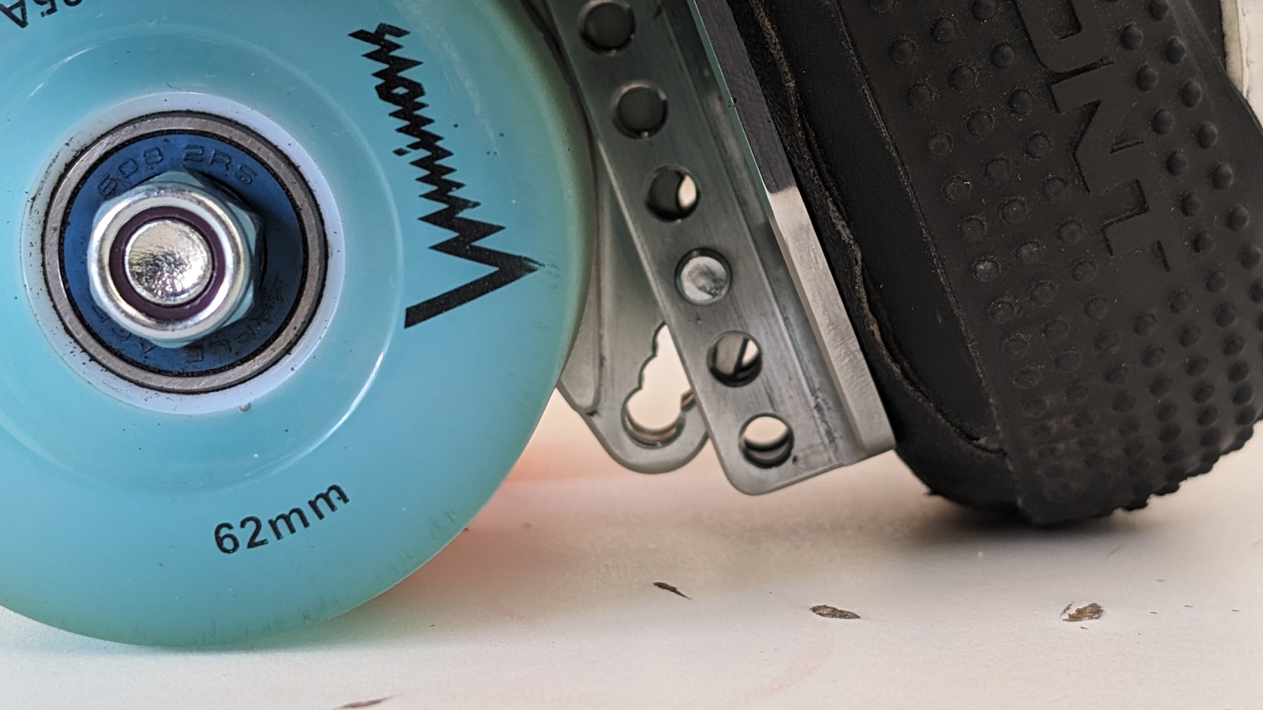
There are some pretty nice details from a machining point of view. There are angle indicating engravings that help with adjustments. There are more machined in chamfers. Some of which are somewhat hard to achieve.
Many chamfers on the rails were actually machined from the “wrong side”, in order to limit the number of setups needed. Each rail was machined in 2 setups. These chamfers came out great, but did (of course) need the stock to be very carefully levelled before machining. Since i was using a stock surface both top and bottom, the exact thickness of the stock was also critical. The nominally 1/8” stock angle was actually 0.131” thick.


Additionally, some of the chamfers on the pivoting blocks had to get really close to the walls, without crashing/rubbing.
Not a perfect blend from the machine, but certainly good enough (and only really visible when zooming way in)


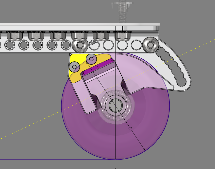
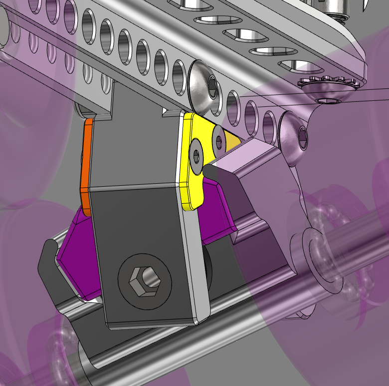
Adjustable Wheel-Bite protection!
Wheel-bite is when the rotating wheel contacts something on the shoe or plate which creates lot of resistance to rolling, jerking the skater off balance.
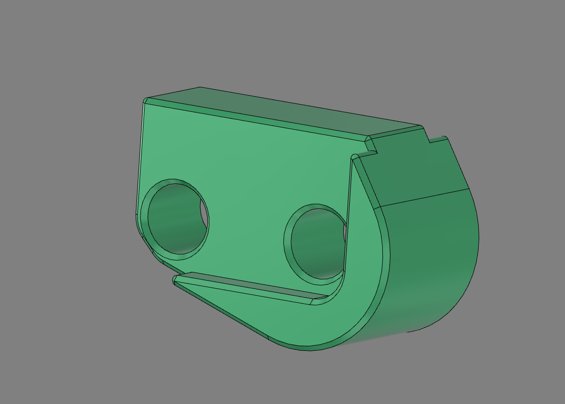
There are little 3d printed shims that can be installed to limit the maximum truck angle, which prevent wheel-bite. They are held in place with some m3 flathead screws.
Since the truck travels in an arc, these shims need to have a matching curving overhang where the truck contacts the shim, otherwise, increasingly thick shims would not have and effect beyond a limit.
The exact shim thickness that someone would want would depend on both the wheel size and steering angle position.


Better toe/heel clearance!
The exact clearance is heavily dependent on the wheel size, position, and steering angle (since more of the truck hanger sticks out at high steering angles).
Toe clearance at 45* is improved enough in a normal-ish setup/mounting that the shoes touches the ground before the plate does. On the rear, the same is technically true, but it’s a minute gap. Suffice it to say that the clearance is improved.
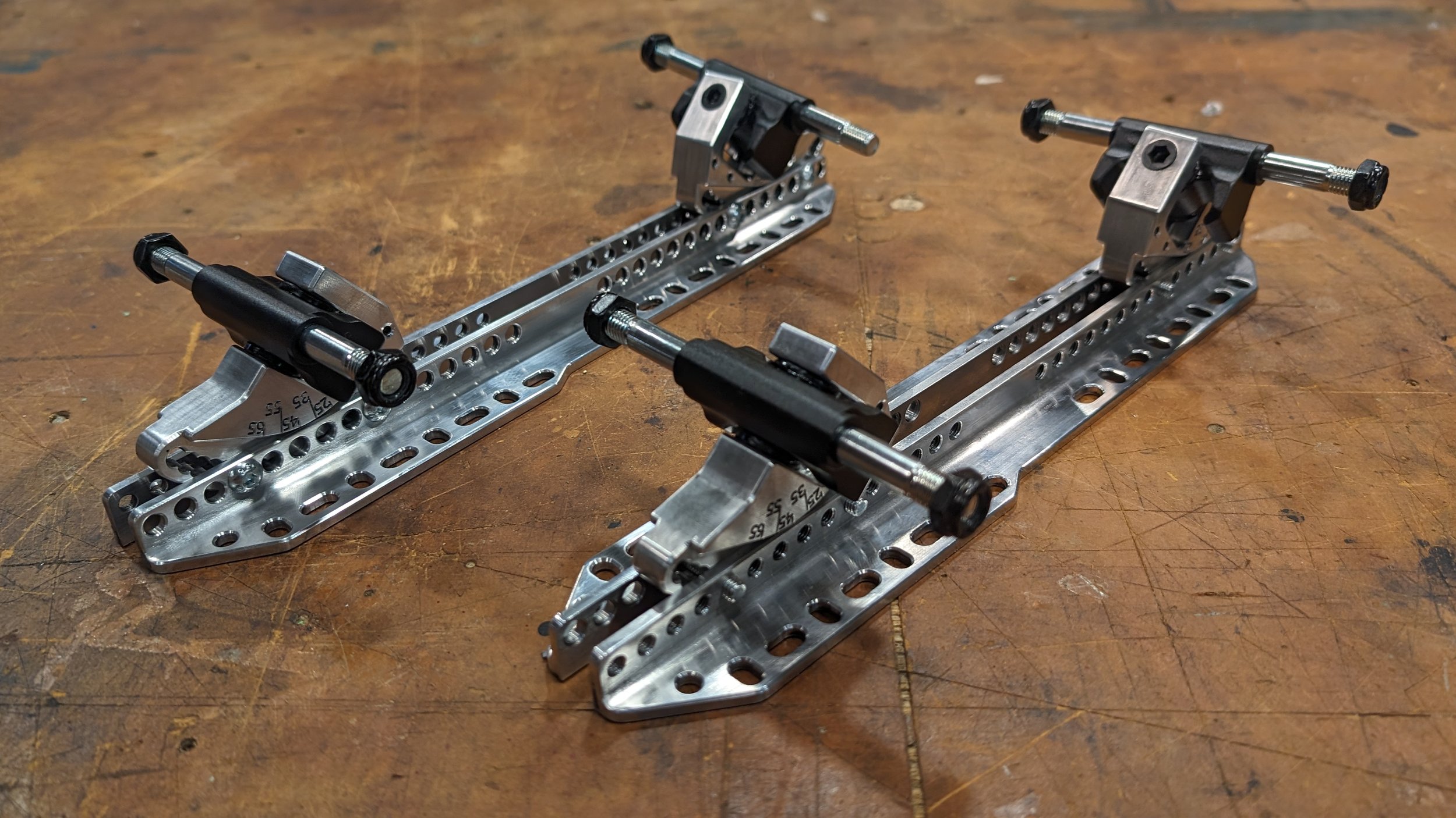
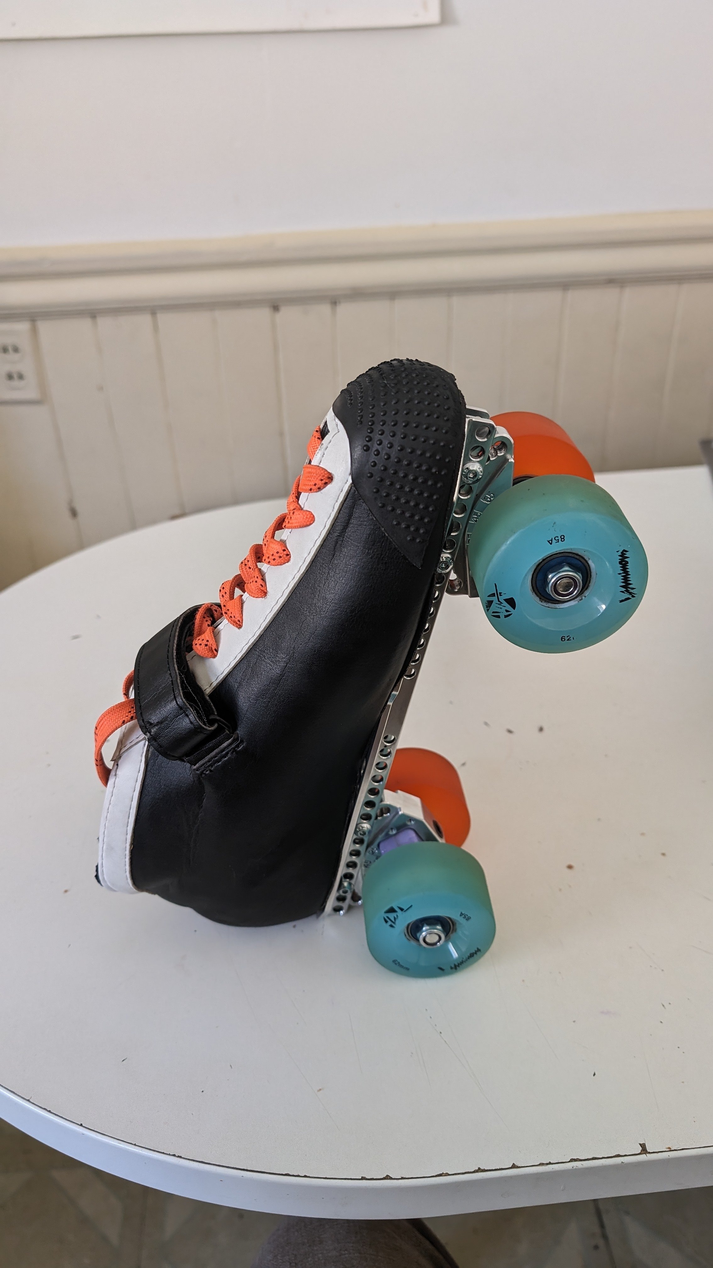
(As pictured, it’s set up with 45* steering angle front and rear, and 2 holes away from the front and back limits of the rails)

Jam Plug compatible!
I designed a little jam plug that can be installed if the setup has 3 empty holes at the front (or back) of the rails. It’s very small, fast to print. It just servs to protect floors from aluminum rails, and the aluminum rails from damaged from floors in certain setups.

This fit is quite nice. Listen to the pop as the axle is pulled out, that means an airtight fit (or close to it).
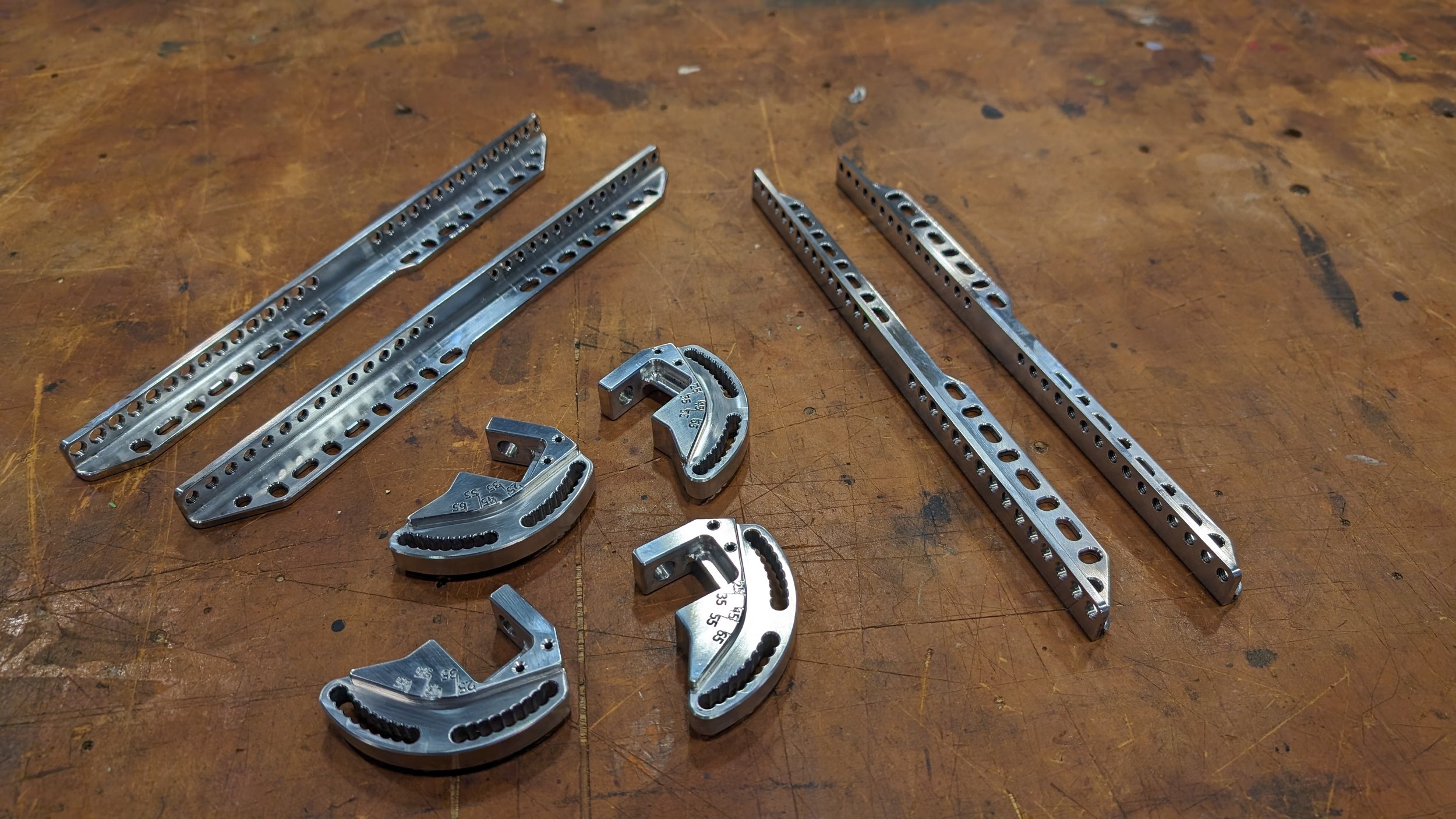
Non-angle-adjustable truck hangers
After riding these skates for some time, i settled into an adjustment that i really liked, overall.
These settings were:
~190mm wheelbase
55* steering angle, front and rear
split cushion stiffness, stiffer in the rear
Larger wheels rear, (50mm front, 57mm rear), which result in a 3.5mm heel lift.
With this in mind, i figured it could make non-angle-adjustable truck hangers, at 55* angle. If these hangers were also lower, then it would allow me to have a non-adjustable hanger at the front, and an adjustable hanger at the rear, giving a heel lift. The hangers would also be lighter, and potentially stiffer.

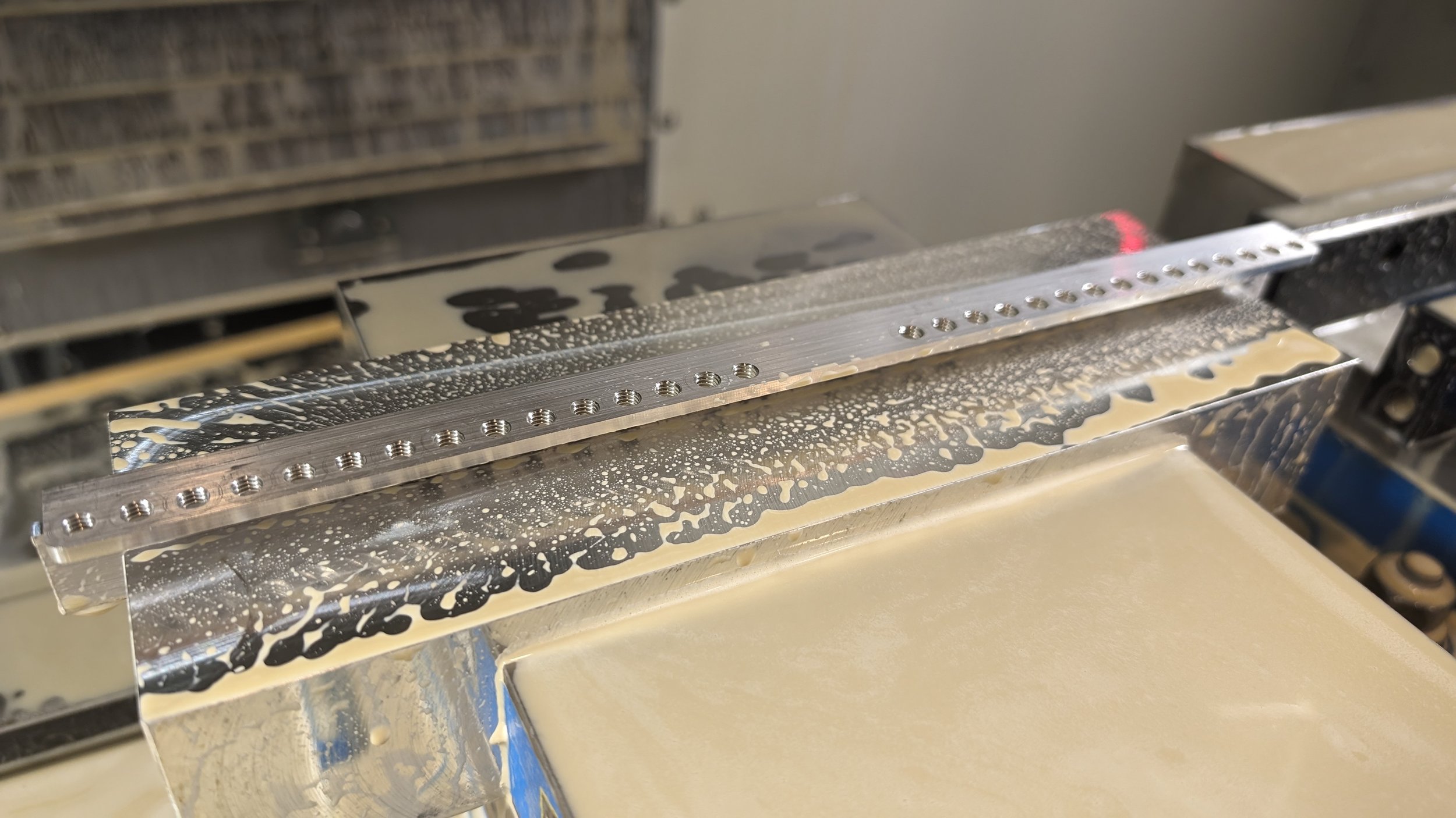
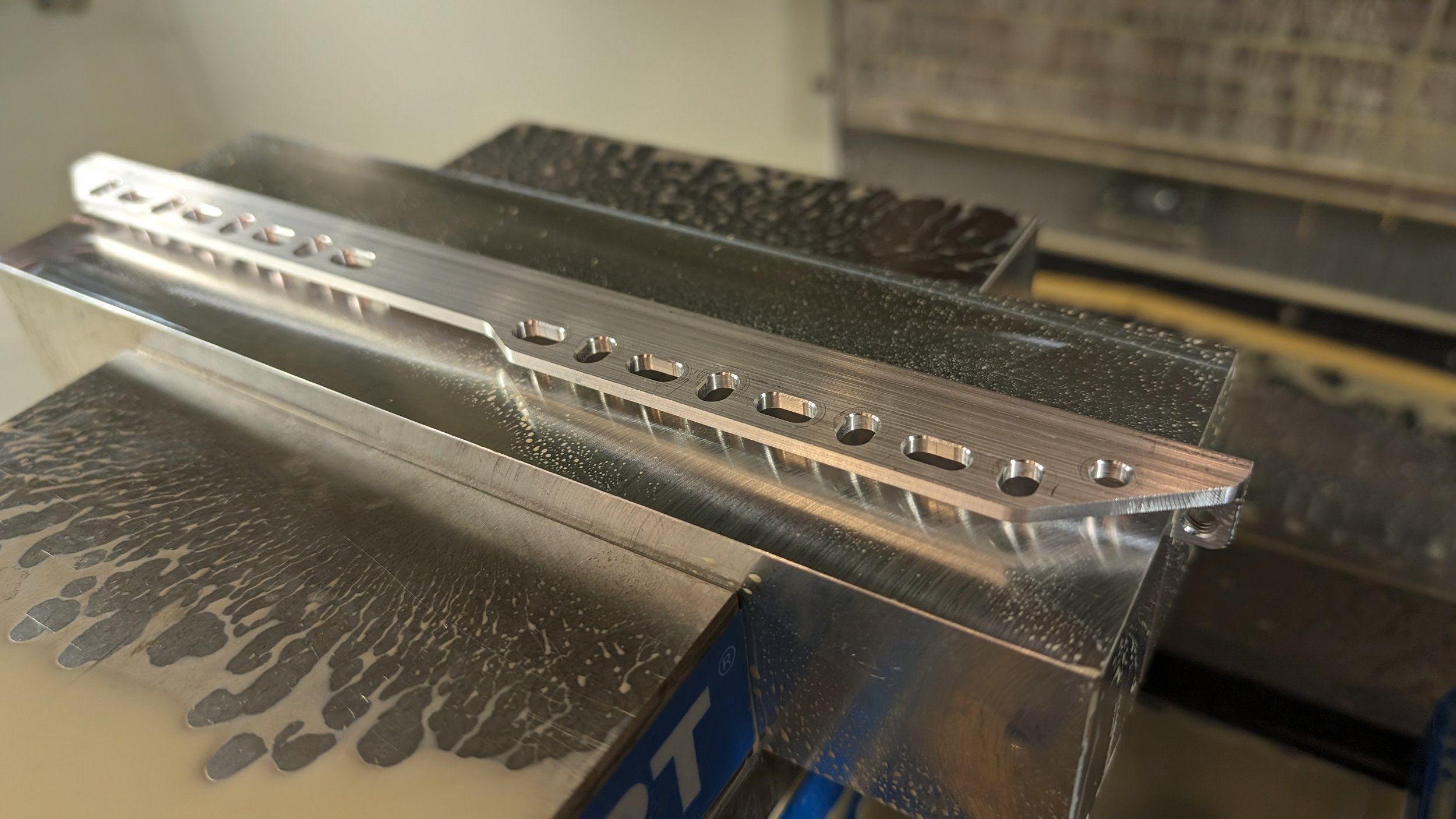
Side 1 machining was the standard fare, and unremarkable
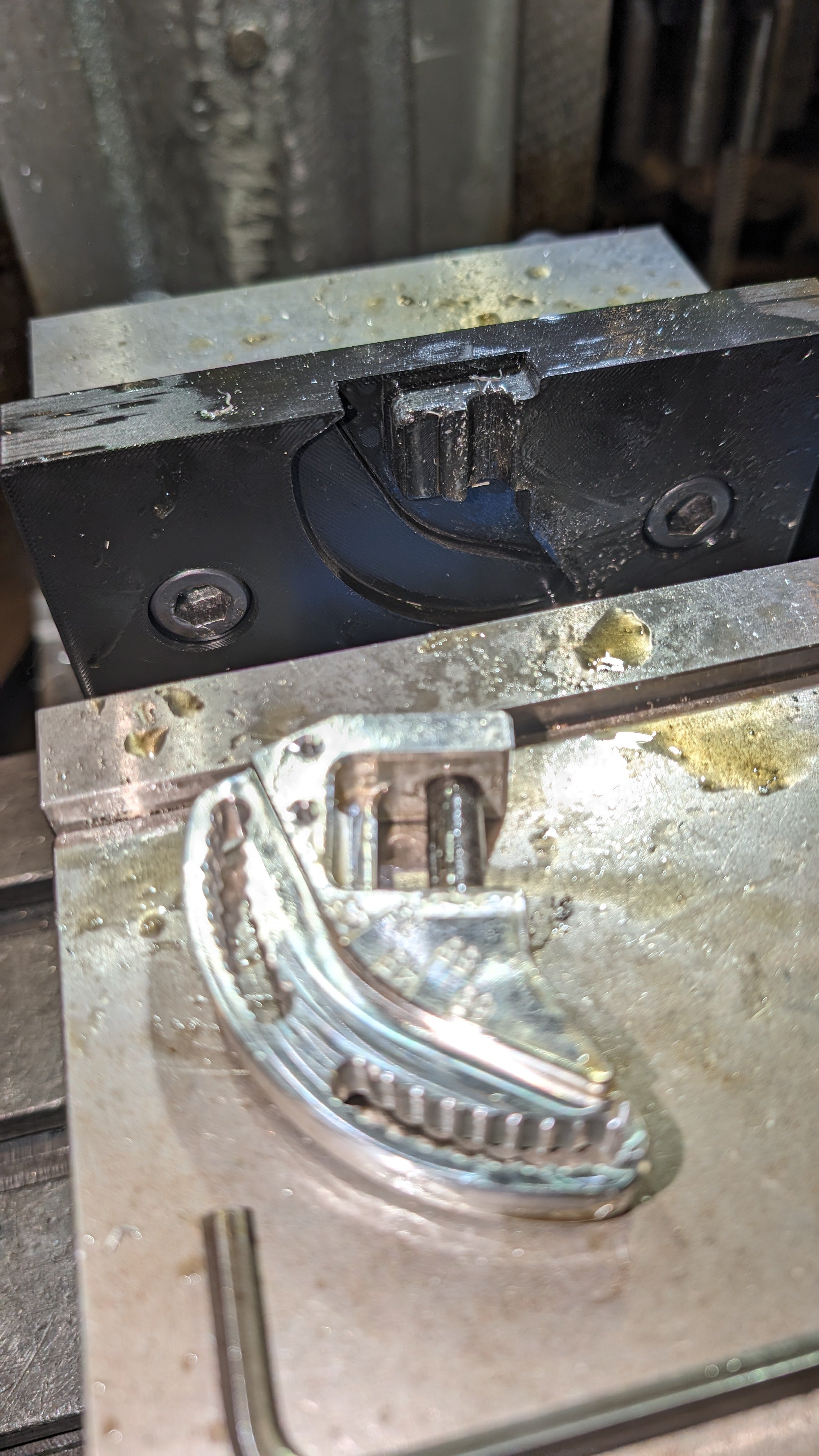
3dp softjaws
However, i wanted fast and cheap workholding for the secondary and tertiary operations.
This time i made all my tooling be 3dp softjaws!
Since i didn’t trust the location precision of fully 3dp softjaws, i wanted to actually probe cut features from side1 instead of relying on softjaw accuracy for location. The problem is that the grip stock is blocking access to all the cut geometry!
I designed some cutouts in the softjaws to allow the Renishaw probe to access the cut surfaces of the part, AFTER the grip stock was machined off.
Since the facing operation to remove the gripstock does not rely on super accurate x/y position, i can use the softjaw part positioning to roughly locate the part, remove the gripstock, and then probe the cut surfaces from side1. The probe reaches into the pockets to clear any potential burr left from the facing. These pockets do need to be blow out to assure there are no chips in them however. This was done manually, but with a little extra work, i could program an air blast to clear them if i do these again, completely automating the in-process measuring.
I was nervous about putting more serious forces on the parts, facing off significant stock, but it worked quite well. Certainly well enough for these low-ish precision parts.
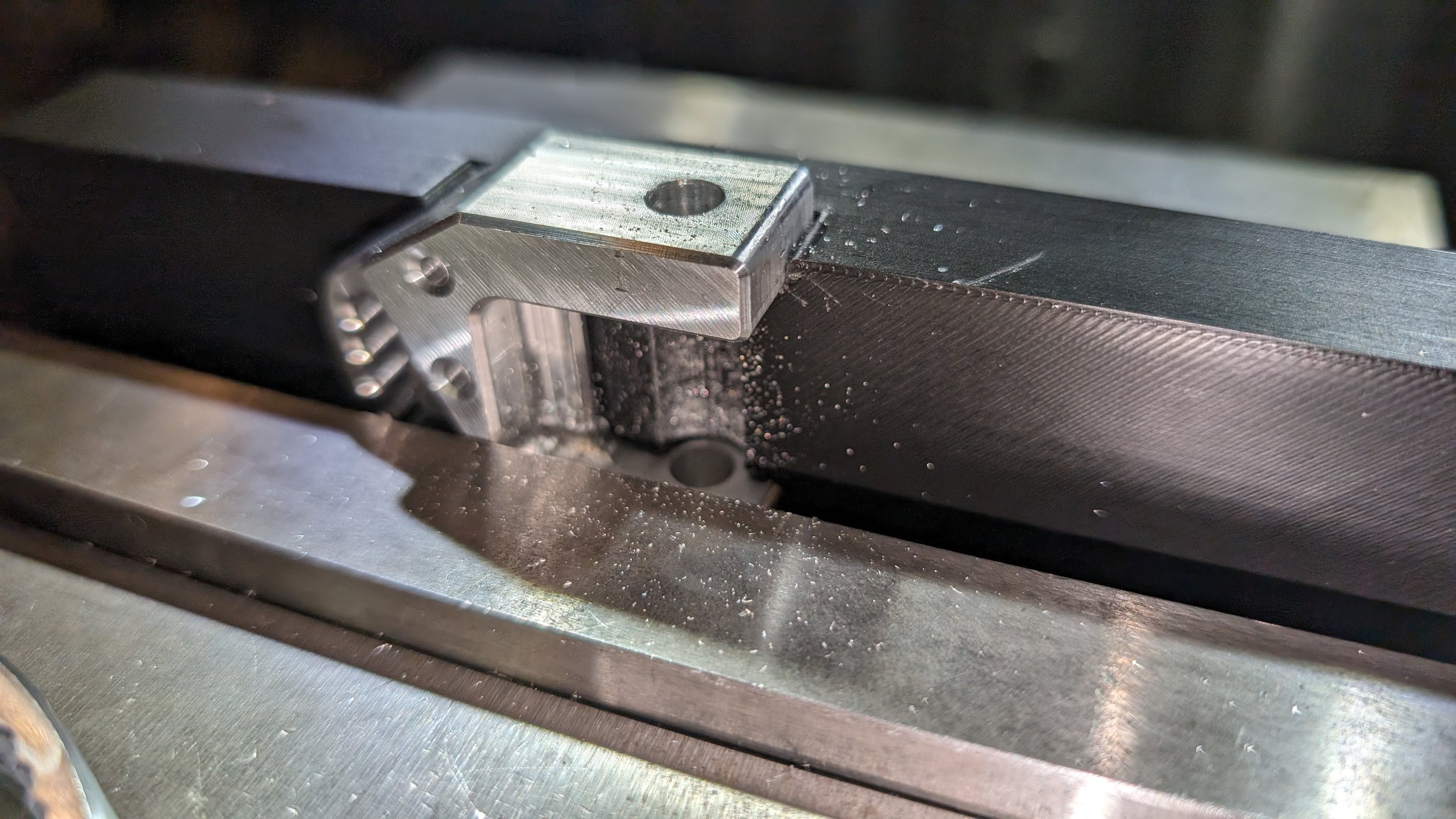
Side 2 chamfer on a side 1 drilled hole. concentricity of the registration is actualy really pretty dang good! The total part is narrower than it shoud be though, but 10 thou (for the first part, will adjust for 2-3). shouldn't matter for this part, but still a limitation of the 3dp softjaws. hard to measure a side1 z feature on side 2. i suppose a work probe that has a hook stylus, but we don't have anything like that. it's getting into CMM territory instead of work probing stuff.
In hindsight of course, i could, and perhaps should/will offset the mounting holes so these non-angle-adjustable hangers can be mounted further forward, without hanging out of the boot so much. Since they don’t need to rotate around the axle, there is no need for mounting hole symmetry on either side of the axle, all i need to the same hole pitch/spacing.
Additionally, there isn’t a good way to access the Z location of any cut geometry from side1, so i have to cut one, measure it, and then offset the subsequent parts to get close to nominal. The 3dp jaw was lifting the part about 0.013” above the nominal Z part origin, so that much was fudged at the controller. For these parts, that level of imprecision in the width is not actually important.
STill to improve/Features to add
While better than that last version, there are still of course, opportunities to improve the design.
Still not super easy to adjust
Still not super easy to read/know the angle position. The engraving is nice, but it’s somewhat blocked by larger wheels. Determining when a line is perpendicular is hard when the engraved line is short and small. Somewhat obviously, you are looking for the line that points between the center two rail holes, not a perpendicular line. Since there are 4 unused holes between the truck hanger mounting bolts, there is a web of material exactly in line with the center of the axle. Of subsequent versions of the rails, there could potentially be a very small notch on this center, to help align the location for easier adjustment.
There isn’t much room or clearance to engrave parallel lines and numbers on the part of the pivoting assembly that is clamped, but if that was possible, it might be a little easier.
It’s hard to get the rear wheel really close to the back of the shoe.
This is mostly because of the spacing between the two clamping bolts. If this spacing was reduced a little, the wheels could get closer to the ends of the rails, which increases adjustment range, and decreases rail stick-out.
This clamping bolts width does directly impact the strength/stiffness of the system though, so we can’t reduce this clamping spacing too much.The bolt spacing needs to be centered on the rails with respect to the pivot location (axle), so it’s not possible to offset the mounting hole locations closer to inside of the skate plate, if using a single set of holes.
Ride comfort is not amazing.
This is intrinsic to the Arius truck system. There is no intrinsic shock absorption, unlike a traditional kingpin system.
Without a lot of compromises and complexity, i’m not sure this is easily solvable, and the plate just needs to be restricted to smoother roads, and/or larger, softer wheels.One can imagine a flexure or pivot with another elastomer under it to independently adjust/control the suspension effect.
Rails are hard to machine.
Each rail is unique, and requires 2 setups each. Since for this test, i was only doing a single set of rails, i didn’t really create a more efficient or foolproof workflow. Each rail operation needed to have it’s origin indicated in, and carefully levelled. With a modification in work holding and machining strategy, i think i could get to a much more automated setup.
I’ll be making a couple more sets of these plates, so i’ll improve the setup soon.This has been improved with some dedicated step jaws, and in-process probing to allow pretty fast and reliable rail cutting.
Cushion-preload.
The stock Arius plates don’t have a mechanism to preload the cushion at all. There is a web that interfaces with the cushion. If this web could be shimmed out, then perhaps the center portion of travel would have more preload.
I think this just means adding some thin shim-stock shims that fold over the web in the truck hanger, but it would be really great to think of a screw thread based adjustment, which doesn’t require shims of different thicknesses and removing the trucks from the hanger.
Vastly over complicated, but a pair or wedges that thread in, and create a variable width web? (sort of like adjustable parallels for machining)
Adjustable Heel Lift
On a subsequent version of the these adjustable plates, I’d love to come up with some mechanism to adjust the heel lift of the plate.
The obvious solution seems to be double the rails per foot, with a pivot at the front, and a jack screw (or something like it) at the rear. This would increase the weight, and width of the skate plate significantly. Stiffness/strength would be a serious challenge too.