
Propulsion System Fabrication 2019
New techniques
After a pretty extensive propeller analysis and motor testing phase, the rest of the pod needed to be designed.
Learning from last year a bit, i wanted to “simplify” the design a bit. The simplest, and therefore (one assumes) most efficient system is to simply have the propeller directly connected to the gearbox, which steps down the speed of the motor from around 4000 rpm to 400 rpm. The big issue with this design of course, is that the motor and gearbox will be underwater! Preventing water ingress, and heat control would be the primary concerns.
Propeller
The propeller fabrication was assumed to have to be cnc’d 6061 aluminum when the design was started. I bought stock, and started programming toolpaths when i thought to myself “how crazy would it be to simply 3d print the propeller and wrap it in carbon fiber?”. The idea here is that most carbon structures in industry aren’t solid carbon, they have lightweight cores that do very little other than hold the carbon surfaces from collapsing toward or away from each other. The vast majority of the stress in most structures is carried by the outside surfaces.
I wanted to try the method, but had very serious doubts about it’s viability. The concerns were
The concave surfaces not being easy to get fibers into, while maintaining some amount of straight, tip-to-tip fiber orientation.
adhesion to the 3d printed plastic.
spline strength.
Dimensional accuracy of the print, and final wrapped part.

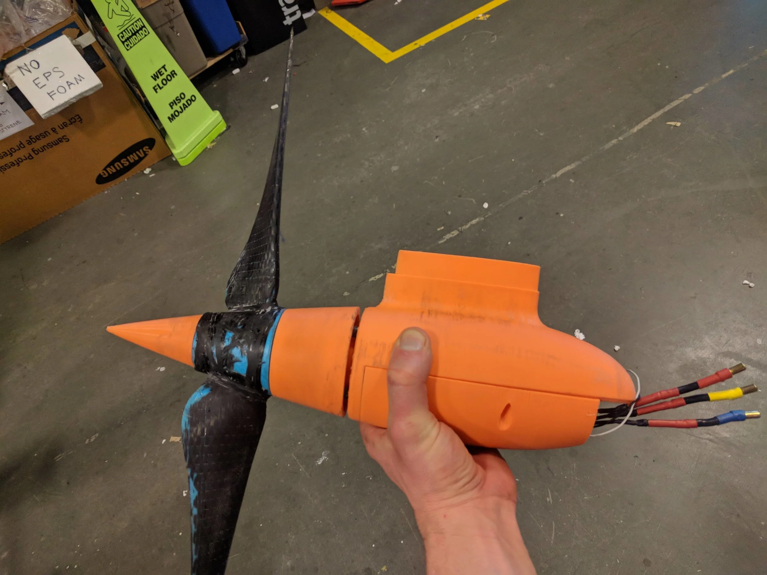
The print was done with a larger than normal 0.6mm nozzle, larger layer heights (0.35mm) but solid infill. Weight isn’t a particular concern, but strength obviously is. The larger layer height and bigger nozzle improve strength, as well as dramatically reduce print time. The increased layer lines are actually a positive byproduct with the wrapping process, since it gives a macro scale surface roughness for the epoxy to sink its teeth into. The surface was additionally roughened with 80 grit sandpaper to create some surface texture for the epoxy.
The wrapping was indeed annoying and difficult to do in the concave surfaces, especially the important fillets where the blades connect to the hub. This first attempt was simply done as a moldless wet layup with no vacuum assist. For the second attempt, i’ll cut more carefully and make better fitting carbon cloth shapes, using a vacuum bagging approach to minimize the deviation from the core/design shape and post-cure finishing. Strength should also improve slightly, though that doesn’t seem to be a concern at the moment.
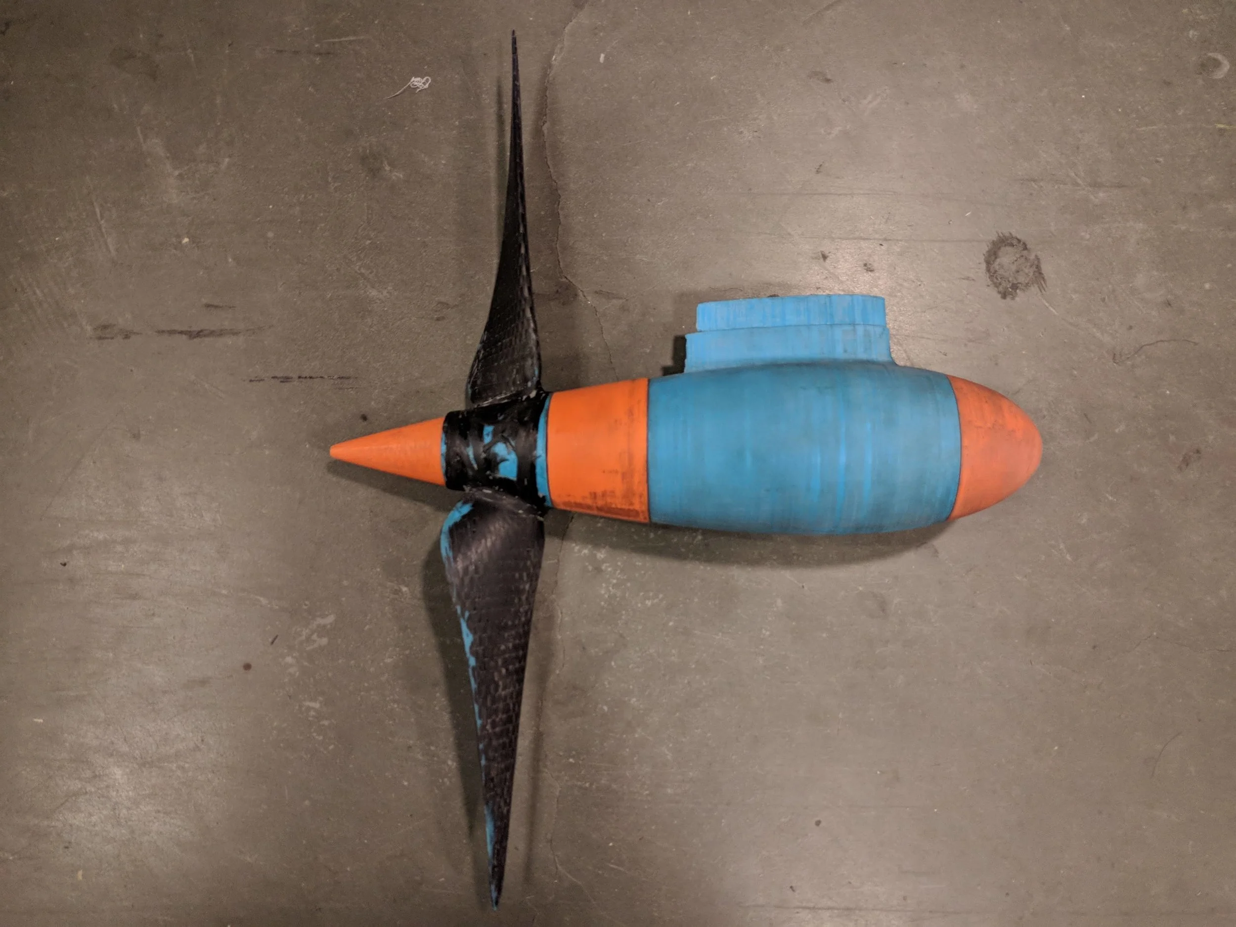
The cured wrapped propeller was sanded back to reveal some of the blue 3d print along the leading and trailing edges. The thought there was about regaining some level of fidelity to the original design shape, and minimizing imbalance between the two blades. This imbalance could create a thrust imbalance, as well as a mass imbalance. By revealing a little of the print, i could be sure i had taken off enough of the flashing.
Initial “does it break?” testing went waaaaay better than expected, and inspired quite a lot of confidence. However, i had no speed control, no measurement of thrust, and the pool boundaries increasing recirculation which lead to reduced applicability of this test. However, the large scale question about feasibility was answered. The 3d printed female splines held up fine too. The answer to the question was “it does not break”.
This was amazing news, since this process is much faster and cheaper than CNCing masters, creating molds, and then laying carbon into the molds. Not as accurate geometry, but maybe 90% similar for the larger areas of the profile, and likely 90% of the predicted performance.
I moved away from assuming i’d CNC the pod like last year, and started to experiment with leveraging much cheaper and (in human time) faster 3d printing techniques. I realised the pod design could be loosened up a bit, because there was no longer the concern about stock cost, crazy long tooling, and massive material removal percentages. I started combining the various individual cnc-able parts into single pieces that could be 3d printed as one. This eliminated many bolts, seal points, and allowed an easier to make, much easier to seal design. Assembly promised, and then proved to be, a PITA, but was possible and the decreased number of seals increased confidence it would be watertight.
I knew heat buildup would be an issue, and i’d planned for both an air inlet and outlet in the pod and strut. I’d done some CFD many months ago on a mockup pod design, and that was worrying, but i (*INCREDIBLE STUPIDLY AND EMBARRASSINGLY*) went with my experience and intuition on what was needed to cool a brushless outrunner. During dyno testing, with no forced air cooling, and no noticeable air movement in the vicinity of the motors, heat buildup wasn’t proving to be an issue. How much different could an enclosed pod with forced air ventilation be?
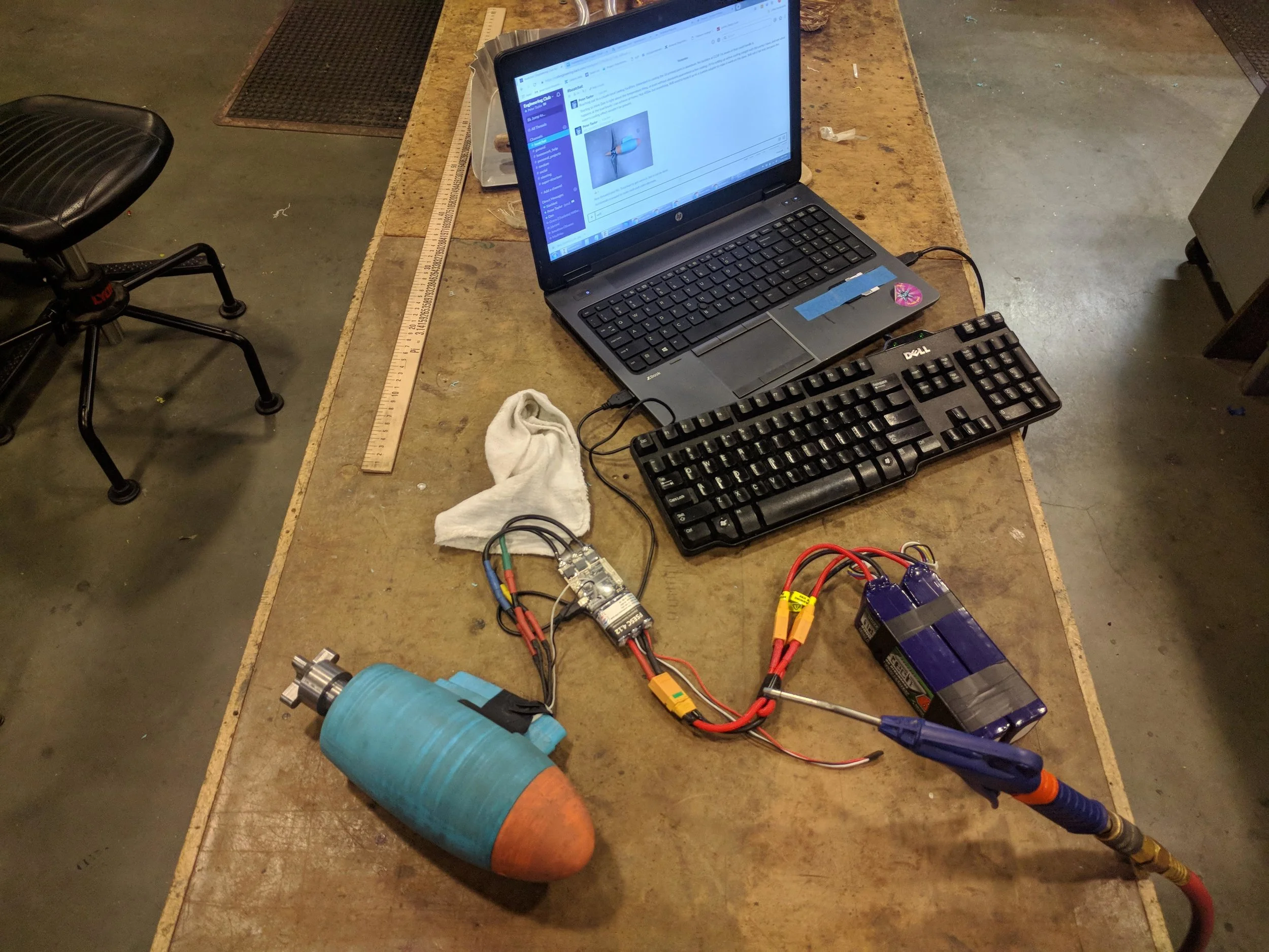
I’d used a thermally-conductive epoxy to attach a thermistor to the coils of the motor. I assumed the little 2 watt parker diaphragm pump i had would be enough to keep the temperature down. Boy was i wrong. The parker pump (which pumped a few liters per minute of air) didn’t seem to make any appreciable difference, so i moved to the shop’s compressed air.
It took the shop’s 90psi air on around 50% max flow to keep the motor’s temperature at 80C, which is really hotter than i want the motor to get. It was a truly untenable amount of airflow, and is just totally unreasonable to spend that much energy on cooling.
With 6 weeks to go before the competition, i had to rethink and rebuild the entire drive system. Not at all the situation i wanted to be in.
After 14 hours in front of the computer the next day, researching, thinking and CAD, i had a new plan. This would be less sexy, a little less efficient, but all the water ingress and heating issues would be irrelevant. I’d simply move the motor and gearbox back up above the water, and use an off-the-shelf right angle drive in a streamlined pod.

Unfortunately it meant redesigning and rebuilding every single part i’d already made, except the motor to planetary coupler (for now…)
The strut needed a much bigger hole for the 5/8 shaft i extended on the angle drive.
The propeller hub needed to change shape because i couldn’t fit it cleanly with the increased size of the new strut.
The pod obviously needed to be totally different.
The good news here was that i chose to use a right angle drive that is an off the shelf part, and relatively well sealed. The propeller hub got smaller, so could have more blade area for the same diameter, or thinner/smaller chord blades with the same area and diameter, which leads to slightly higher efficiency. Waterproofing also wasn’t an important issue, and there was not much heat buildup, partly because cooling could be direct water contact.
There was also much more space and passive air cooling for the motor and gearbox.
I decided to try to simplify things a bit also by using a trantorque on the propeller. This eliminated the need to make a custom spline coupler, though i printed a spline into the propeller as a backup, in case the trantorque slipped. The trantorque tests went fine, with the propeller and pod in a large trash can full of water. Input power beyond what we can see in the competition, and no slipping in the short term. I was torquing it to much less than it’s spec, since i didn’t want to crack the PLA plastic bore from the expansion of the coupler, which is where the uncertainty in the applicability of a trantorque came from. I was also concerned about the plastic moving over time, and loosening up during the course of the day.


The last big discovery/change that i think is interesting (sorta) to read about is the gear reduction. With no load and 100% throttle the motor seems to draw around 50-60watts. The Apex Dynamics AE070 10:1 planetary gearbox i’d designed around listed a 97% efficiency on the datasheet. That’s pretty sweet, and it’s hard to image much better than that.
With the gearbox attached, and the motor again at 100% throttle the system was now reporting a draw of around 110-120watts! What’s this? It seems that the datasheet describes a best case efficiency, at maximum rated torque, perhaps at a very low rpm. At higher speeds, it seems that there is more like a relatively constant power loss of 50-60w. If you’re running 2000w into the system, and the loss is 60w, that’s the 3% the datasheet points out. If you’re running 400w through the system, 60w is 15% of the total power! A 15% loss is pretty lame in a game that’s all about efficiency.
With about a week before the competition, i decided to build a new gear reduction. This would use the same source of high reduction spur gears as i’d used 2 year ago. Huge radio controlled helicopters. These things have 1.5 meter plus rotors (5 feet!), and motors that are a few HP, so the gears should handle our application, even though we’re running a lower rpm, which will mean higher torque than they’re really designed for.
I took a bit of a risk with regard to mounting. The spur gear came with a 6mm bore, and all the motor’s i’d been using have an 8mm shaft. There wasn’t nearly enough meat to bore out the 6mm to 8mm. That meant a long stick-out reducer. Since the parts are designed to be used in an existing system, and the helix angle is unknown, it’s really hard to measure an exact center distance between the gears for a good mesh. that meant an adjustable center distance solution, which is hard to implement simply with a shaft supported on both ends of the gears.
I took a chance, and designed a system that had quite a lot of flex potential, and hoped that the force driving the gears apart would be less than the restoring force of the flexed shafts, threaded rod, and plywood plates. Luckily, i was right. The adjustment allowed a nice tight mesh, and there was no sign of the gears flexing away from each other, even though both gears were cantilevered out in space. The laser cut plates allowed 2 or 3 assembly types to be tried without redesign or recutting the plates. Below you can see the bearing mounted in the lower plate that would have allowed a fixed center distance and support on both ends of the motor shaft.

With the first test of this new gear reduction done the night before the drive up to the competition (with the planetary solution as a backup), nerves were high, but the payoff was huge. The motor with gear reduction was showing around 50w of power loss at full throttle. The numbers aren’t totally apples to apples, because i selected a slightly different motor because of shaft diameter tolerances and slightly different ratios (heli gears 9.33:1 vs planetary at 10:1), and the speed controller’s poor accuracy power sampling. However, the numbers were very much better than the planetary gears, so i decided to run this system on race day.
In part due to the rest of the team’s disorganization and late start, there was no on the water testing of anything. Race day morning was the first time i got to see how well everything worked, which is not at all how i want to operate. There were bugs and omissions in my design. If we’d had even one real dry run, we’d could have discovered that i’d under-torqued the trantorque that couples the 112t delrin gear to the 5/8 shaft. That started slipping in our endurance race, which meant a 4th place time, rather than having a shot at winning that event. We lost at least a few laps, and didn’t drain our batteries as we should have. I managed to tighten up that trantorque at the midpoint of the race, but we still only managed 14 laps, with the winners getting 18. However, the lap time of our last lap (where the batteries would be lowest, which should lead to the slowest lap) extrapolated out to the entire race length would mean 28 laps! The boat was fast, but a lack of organization/support on the team meant this kind of simple failure is hard to catch. Frustrating.
Our sprint times were phenomenally better than last year’s, and those too might have been affected by the slipping trantorque. They were both recorded prior to the slipping trantorque being discovered. In 2018 our fastest sprint was 42 seconds. This year, our fastest sprint was 29 seconds, a course record, as far as i’m aware. That’s over 30% decrease in time! I’d call that a success.


