Manual Lathe Live Tool
I’m not 100% sure why i wanted to build this thing.
Partly I’m lazy, and wanted the ability to quickly pop some cross drilled holes in a part on the lathe, without moving it over to the mill.
Partly I wanted to be able to do some light duty (dremel type) grinding on the lathe, for things that are really hard. Modifying carbide endmills, for instance.
Partly I wanted to build something in the real world, rather than in CAD (covid and endless CAD work for the explo has really taken a toll on me).
Partly I like things that are a little on the dangerous side, or outside the realm of complete comfort.
I wanted to make something with parts and materials i already had. Motor, controller, belt, 1 pulley were already on the shelf. I bought the plate aluminum, and the rest was scrap material.
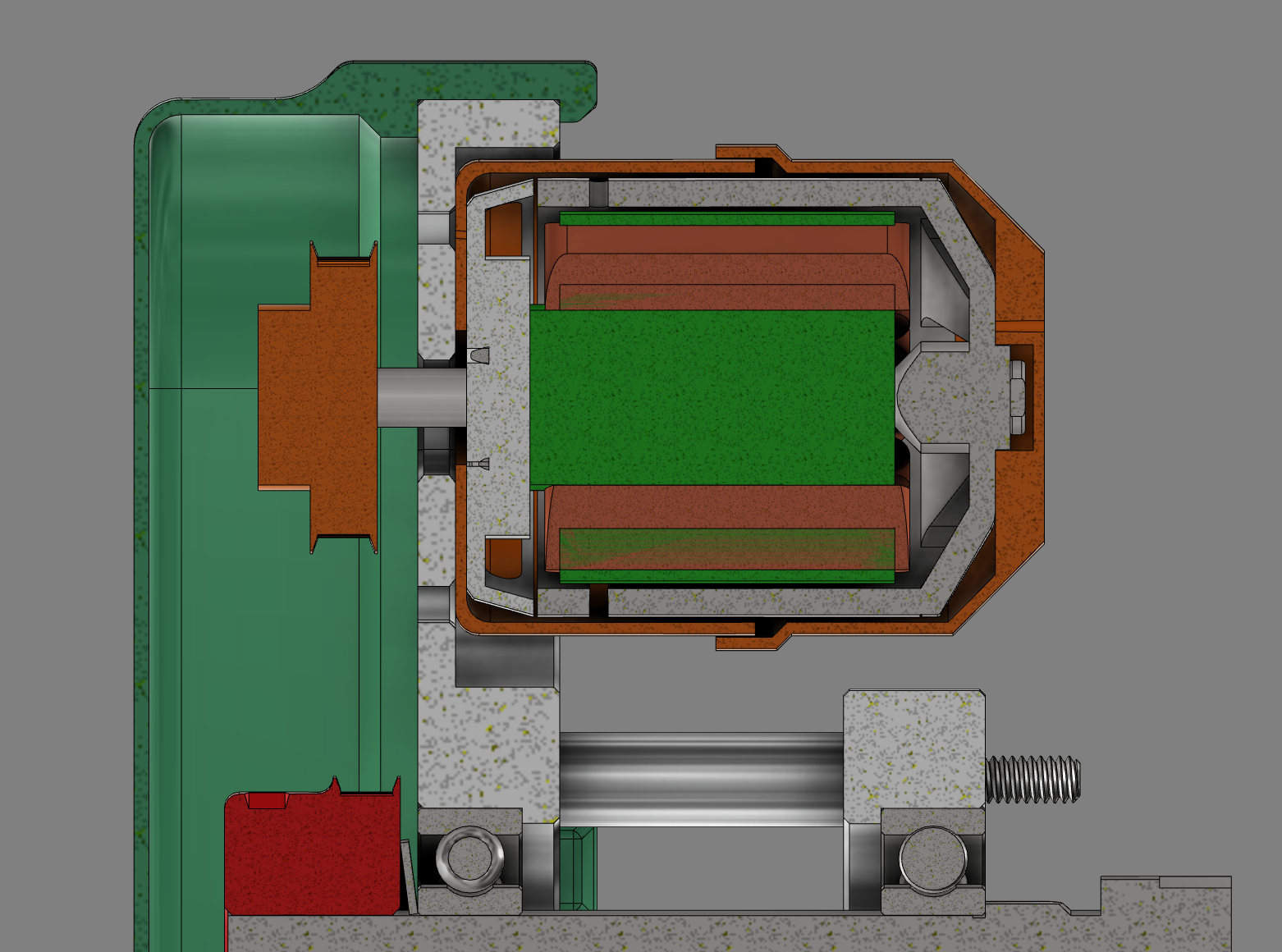
Basically, this is an ER16 collet spindle, with a powerful brushless motor, some big bearings to support reasonable loads, and a way to attach to a Quick Change Tool Post.
While i didn’t test the actual power consumption, the last version was limited to 40amps, at around 40v, which means around 1600w (a little over 2hp)!
I’ve run a 3/8 endmill in aluminum a little over 1xD around 10krpm, and that didn’t bog down the spindle, so there is some oomph behind this little guy.
Power Transfer
Power transfer is via a common gt2 belt, and i’m really at the very edge (or beyond) what it can or should do, but there is also something fun about that. I’ll move up to a burlier belt if/when that become necessary. For now, the cheap little belt is going well.
I designed a parametric GT2 pulley, which is rotationally symmetric (+/- a tooth, depending on tooth count), for decent balance. I designed in some overhanging bridge supports, but those generated by Cura were as good or better.
The tooth shape was derived from the official GT2 spec, and scales parametrically with the number of teeth (since the tooth shape changed with diameter, just like a spur gear). I was a little worried about clamping force, but that seems to be fine for this application, which is high speed, low-ish torque.
Protection
I made a labyrinth seal to stop chips getting into the spinning motor can (it’s an outrunner, with holes for cooling). This does mean I need to watch the temperature somewhat. No sustained milling with this setup. Duty cycle somewhere in the 10% range (When at 1600w), I’d think, since the plastic is low melting temp, and the motor has really poor cooling now.
I also made a printed plastic shield to protect the operator from getting something stuck in the fast moving belt.
Next steps
I think the cover should really have had some through holes rather than little clips, which would mean a few tapped holes in the aluminum plate below it.
Some sort of user interface. Tachometer and mount for the speed control knob.
Better protection for the speed controller from chips. Integrate into a new cover that houses the user interface?
An AC->DC converter makes more sense than batter power, though the current motor and controller and low voltage, high current models, so a 40a AC->DC SMPS is kinda expensive for something like this, particularly since most of the parts i already had for this build.