Duelling motors Dyno
Three runs testing the Turnigy sk3 260kv. Blue point are full scale (0-100) to give an idea of overall shape, orange are scaled/zoomed axes to accentuate differences.
As part of the CCSF solar regatta project, i needed to be able to pick an efficient motor, and run it at its optimal point. Datasheets for R/C motors are largely non-existent, but they are generally quite efficient, cheap, and there are lots of options available.
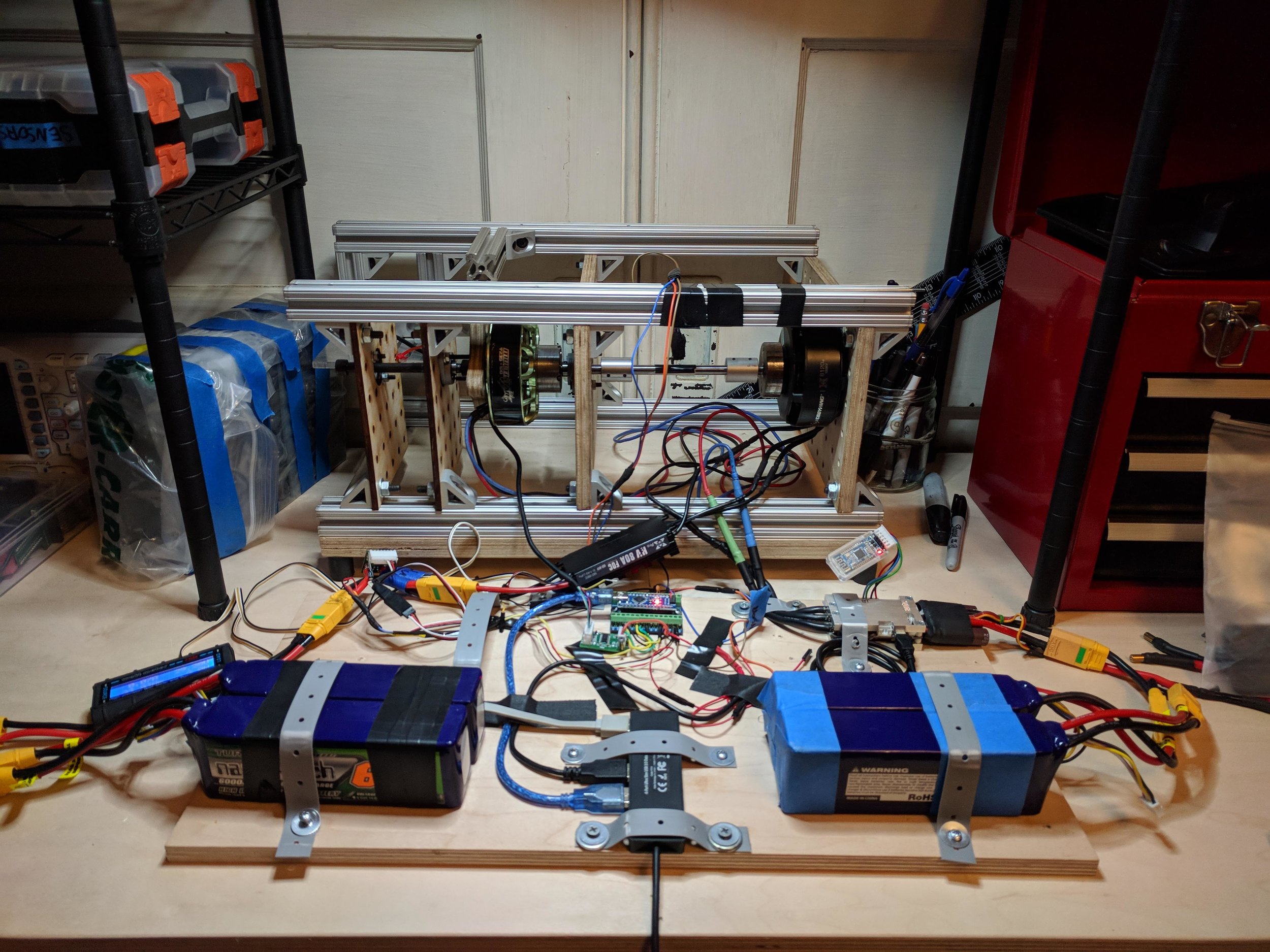
This dynamometer uses two motors, and two motor controllers. The first is the motor under test. It is controlled by an arduino which monitors its current and voltage and enacts a power limit, which allows me to easily simulate the maximum (and ideal) power point on the solar panel’s IV curve. This point is approximately 30 volts and 15 amps, for a power of 450 watts. Assuming we can control the panels and load them effectively to keep them at this point, we should be getting the most power to the motor controller.
This test motor’s output shaft is directly coupled to another similar motor’s shaft that is used as a regenerative brake or variable load. This absorption of power creates a torque.
The test motor is not mounted in the regular way, but is instead suspended by it’s rotating shaft, with it’s base attached to a lever arm that’s exactly 6 inches long. When braking, this arm exerts a force on a load cell, which measures the reaction force between the two motors. It doesn’t matter much whether this torque arm is attached to the motor under test, or the brake motor, the reaction torque between them will be the same (newton’s third law being a law, after all). There is one bearing reducing the torque slightly if the brake motor is the one attached to the torque arm. The load cell communicates with an arduino, which communicates via a serial connection with the host.
There is a python script marshalling the two motor controllers and an arduino with voltage, current, load cell and rpm sensors. This script juggles the three serial connections, tares the scale at bottom and top of test rpm range, averages sample groups, tracks sample history and calculates standard deviation of sample groups.
The program logic follows this flow.
User is asked if they want to calibrate the scale with a known weight/force. If not, the default/previous stored calibration is used.
The test motor spins up to the top of the test rpm range, the brake motor gradually increases its brake current until the test motor is loaded to the power limit in its controller (450 watts in our case).
From here, the scripts repeats the following steps until a break condition is reached. (Low rpm limit reached, charged battery voltage too high, test motor battery voltage too low, brake current on either motor beyond programmed maximum spec, etc).
Take x samples in a row, test standard deviation of the rpm of these samples. If the deviation is lower than a percentage of the average speed, then record the a bunch of collected data, most importantly, the rpm, power in, force/torque. This data allows a calculation of mechanical power output, which is compared to the electrical input to get an efficiency.
Increase brake current by an appropriate amount (less for high rpms, more for lower rpms)
If the rpm will not stabilize within 100 samples, it is skipped and the next brake current level is tested.
After an end condition is met, the program cleans up, writes the data to a csv file and releases the serial connections.
With the csv imported into excel, graphs are made to visualize and compare the motors.


Switching frequency investigation
The VESC motor controllers allow a bevvy of options, and some of these might impact performance. The MOSFET switching frequency is one of these options. Initially i expected this to not have an effect on the performance of any given motor, but it seems i’ve discovered that the default 20khz frequency is preferred either in the firmware or hardware. It’s not yet clear why, or what component is causing the degradation in efficiency away from this frequency.
The earlier versions of this dyno were using the VESC itself as a current, voltage and RPM sensor. It turns out that the current into the controller is back-calculated from phase current, and that phase current isn’t captured very accurately. This means that the numbers aren’t very accurate. Additionally, there seems to be a bug in the firmware or limitation in the hardware which means different switching frequencies don’t report their true currents. That meant that the dyno had to involve into having external current, voltage, rpm and power limitation (vesc has definable internal watt limit, but is based on bad measurements). This also opened up the dyno to test controllers other than the vesc.
Dyno runs at differing MOSFET switching frequencies, Hobbywing x-rotor 8120-100kv.
Dyno runs at differing MOSFET switching frequencies, Turnigy Multistar 9235-100kv.
relevance to propeller design
Once a motor and optimal rpm are selected, the gearbox can be designed to take this higher rpm down to the lower, optimal operating point of a custom propeller to round out the trifecta of important efficiency curves: Solar Panel, Motor, and Propeller.

A previous setup with two higher kv motors. Red motor had a custom 6mm-8mm shaft coupler made to be super stout, concentric and parallel.
Going further
For those that want a little more detail, i was talking to some folks about this over on the VESC forums. Check the thread out here:
https://electric-skateboard.builders/t/changing-foc-switching-frequency/30928/181
and a tiny bit here:
https://vesc-project.com/node/658