custom papr project
The problem
A PAPR system (powered air purifying respirator) is probably the very best form of protection against covid infection, excluding simply not coming into contact with the virus in the first place.
Commercial PAPR system were/are totally unavailable during the Pandemic, and even if they could be purchased, they are expensive. People like dentists do not have access to professionally made PAPR systems, but they get really, really close to mouths, and use compressed air. There is no way that mechanical barriers would be enough to protect them, and even n95 masks only filter >95% of the virus from the air. A good PAPR system filters >99.99%, at least 500 times better filtration!
This project was incredibly challenging and frustrating. The biggest challenge was in sourcing appropriate, trusted filters that were readily available, and had a low enough resistance to flow.
Filter breakthrough
After pummeling a wall with my head looking for a good low resistance, high viral filter efficiency, readily available filter media Gaia had the idea that the ubiquitous ISO 15/22 viral filters could be used in parallel. That would mean cutting the total flow resistance by 1/n, as well as getting the flow rates we need for a loose fitting PAPR mask without blowing path the flow rates the filters list on the datasheet.
While we had easy access to Chinese knock-off filters, getting the same filter brands used in hospitals was much, much harder. We progressed with testing on the chinese filters, expecting that the more reputable ones would perform comparably.
The fan
At first, i assumed that an axial fan design would not develop nearly enough pressure to get decent flow past the filter. However, thanks to Digikey’s excellent Parametric search, i managed to identify a whole series of inexpensive fans that ticked all the boxes. The Sanyo Denki 40mmx28mm fans developed plenty of pressure, good flow rates, were reasonably efficient, quiet enough, small, and had both tachometer and a PWM speed control input. Their datasheets also had excellent pressure/flow curves at different voltages and duty cycles. The Sanyo Denki fan catalog is almost 700 pages long! Good stuff.
Control circuit
I designed a simple PCB to allow the buck regulator, piezo buzzer, voltage divider, filter capacitor and various connectors to be compactly installed.
The main requirement for the fan was to have a 25 Khz PWM signal that responded to some amount of user input to adjust the flow rate. The max-air capr has three modes, low, medium, high. I opted to go instead with a potentiometer to allow finer adjustment between baked limits. The easiest, lowest power way i could think to do this was with a teensy, but under-clocking the core dramatically to 2 Mhz. Here is was drawing in the 2 mA range (including the potentiometer current draw), which is less that 1% of the total system power. Had i pushed harder, i could have implemented frequent sleep cycles, to lower the power consumption much further, but the fan was the big drain, and so long as the control circuit didn’t consume more than a percent or two, i was happy.
For low voltage warning, i used a simple voltage divider. On a v2, this would probably also have some amount of adjust-ability, through jumpers or dip switches. The idea would be to have a selectable low voltage warning for various voltages that are appropriate for various power sources. AA NIMH, AA disposable, and LIPO should all warn at different levels.
Currently the teensy is measuring the fan speed through the tachometer, but is not doing anything with that information. Comparing fan speed to commanded duty cycle, one should be able to detect a badly fitting mask, or loaded filters with deviation from the expected relationship (above or below respectively). A current shunt would also be useful on a v2, to have that data.
Since the design is supposed to be used with various filters, power sources, some of these features become unreasonable.
Testing
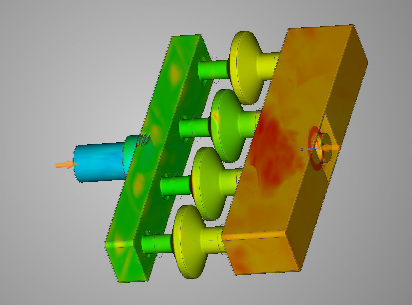
We did a lot of testing of airflow with various setups. We compared a CNC cut version with filters in a 1x4 arrangement, a 2x2 CNC version, and a few iterations of 3d printed 2x2 manifolds.
Testing data is available here: https://docs.google.com/spreadsheets/d/19FxDHTY_sTQufdw73h-cg2914ezn83u6DAY_D5Sbg0A/edit?usp=sharing
I also made a single filter pressure drop test rig. I wanted to be able to compare the available Chinese filters with the datasheets for the reputable brands.
Filter catastrophe
Unfortunately, the most common reputable filter model is dramatically more flow restrictive than the Chinese filters, roughly double at the target 60 L/min flow rate. This means a pretty significant rethink. Double the pressure is much more than double the fan power. We could increase the filter count, but the 4x filters are already unwieldy, 8x would be utterly insane. Additionally, the low cost per filter starts to be diminished when you have so many of them.
Burnout had absolutely set in at this point (3 months of full-time regular work, plus all the covid projects wore me down), and the project stalled. Cases in California/Bay Area have stabilized, and the immediate need is seemingly less pressing. I’ll take a breather, and re-analyse the problem at some point in the near future.